Drifting Recorders
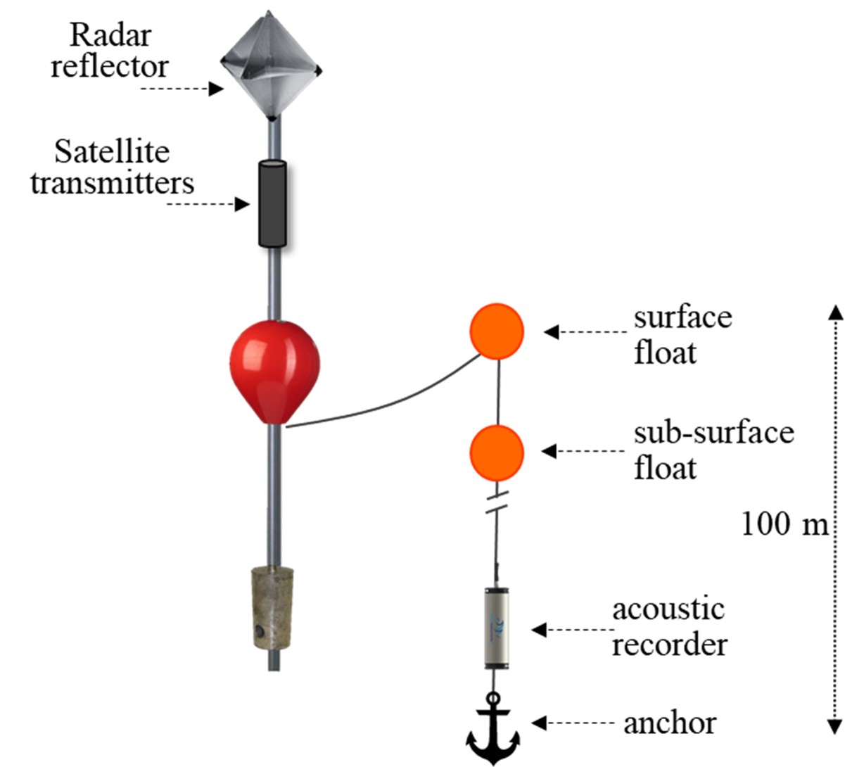
Drifting recorders consist of a hydrophone array and autonomous recorder at depth with a surface buoy and satellite GPS at the surface to allow for tracking and retrieval (Figure 1). Components are continually modified to address problems and accommodate improved technologies.
The surface buoy transitioned from a spar buoy to a high-flyer pole buoy after CCES and prior to Adrift in an effort to minimize buoy loss due to ship strike. The pole buoy includes a radar reflector for visibility and a satellite GPS tracker mounted to the pole. Pole buoys included the now discontinued Lindgren-Pitman high-flyer buoy, a custom high-flyer developed by Fisherman Dick Ogg, and a custom in-house high-flyer pole buoy.
Initial GPS trackers included two SPOT GPS trackers (for redundancy) mounted in a waterproof canister on the pole buoy. The modifications made to these trackers to increase their battery power led to increased failure (modifications weakened the units). These were replaced with Solar GPS that were easier to use, more robust, and could be used for extended periods with solar recharge of the internal battery.
A trawl float was attached to the surface buoy with a short length of floating line to allow for retrieval using a grappling hook.
The hydrophone array, recorder, and ancillary components were deployed vertically from the surface trawl float, with the hydrophone array and recorder located 100 or 150 m depth. While movement of the surface buoys would be affected by wind, variable surface currents, and swell height, instrumentation at depth were minimally affected by modest and relatively stable subsurface current. The different forces at the surface and depth occasionally led to strumming of the line and hydrophones. Additional ancillary components were added in 2022 to minimize vertical and horizontal movement of the instruments, reduce tension induced strumming, and reduce displacement of hydrophones from a vertical orientation. Also, several initial losses were due (at least in part) to failures in the primary vertical line; this line was replaced with a significantly stronger line that eliminated this failure point.
To improve vertical alignment of the hydrophones at depth, a subsurface trawl float was placed immediately above the instruments, with a 30 lb mushroom anchor below the instruments. This effectively reduced vertical displacement of the hydrophone array. A small drogue was used to decrease horizontal movement of the hydrophone array at depth, and a dampener plate was used to minimize vertical movement. While these helped alleviate tension and movement that attributed to strumming noise, an additional bungee was added to the line to further reduce strumming. The anchor was attached using a small rope with low breaking strength as a ‘weak-link’ to mitigate entanglement risk.
The acoustic recording equipment consisted of a two-element vertical hydrophone array below the recorder. A Sensus Ultra depth sensor was attached directly above the top hydrophone and recorded depth at 60s intervals. The top hydrophone consisted of an HTI-92WB and the lower hydrophone consisted of an HTI-96min positioned 5m below the top hydrophone. Recorders consisted of either the (now discontinued) SoundTrap 4300 or the SoundTrap 640 which allowed for extended deployments (Ocean Instruments, NZ).
Initial recordings included a duty cycle to extend deployment, and then all recordings shifted to continuous sampling. Sample rate varied according to the instrument, with a minimum sample rate of 288 kHz. A summary of deployment details can be found in Adrift Expanded Datasets.
More information on drifting recorder components and design can be found on ourAdrift Field Methods website. Methods for drifting recorders deployed during PASCAL and CCES can be found in their respective reports (Keating et al. 2018) (Simonis 2020).
Results
Clustered drifting recorders provide an opportunity to improve our understanding of the spatial and temporal variability of the contributors to the soundscape. Preliminary results suggest that clustered drifting recorders can be used to reduce the possible range of sound source location (see Modeling Habitat Use) and can provide information on the spatial variation in soundscape (see Spatial Variation in Noise). Drifting recorders were deployed in clusters of 4 in Humboldt and Oregon study areas, and in clusters of 8 in the Morro Bay Study area. In some cases, drifting recorders in close proximity to each other followed dramatically different drift trajectories.
There were multiple cases of equipment and data loss, especially during the initial deployments. Losses were due to a variety of reasons, including inclement weather, strong currents, and recorder failures. We mitigated these problems through modifying components and altering survey methods. A number of gear modifications were made to improve robustness and to decrease self-noise that interfered with recording quality. We recommend additional buoy modification to reduce noise associated with strong currents and inclement weather. Southwest Fisheries Science Center (SWFSC) will be using an alternative buoy design developed by Pacific Islands Fisheries Science Center during the CalCurCEAS 2024 survey, which may reduce strumming noise.
Drifting acoustic recorders are not appropriate for all geographic regions. We recommend conducting a regional pilot study to determine the region-specific environmental conditions, and to identify local partners. The Humboldt study area was especially affected by strong currents combined with the close proximity of the study area to Cape Mendocino, in which options for retrieval south of Cape Mendocino are rare. The success of the CCC-PAM survey in Morro Bay included the financial benefit of sharing vessel resources, improved scientific collaborations, and it provided an opportunity for scientists to share and learn from other community members. We recommend consideration of a collaborative fieldwork pilot study in Humboldt and other regions.
There were multiple recorder failures, and different problems were associated with different recording models, including: failure to start, instrument flooding, and low received levels on one or more channels. Initial deployments (including the previous PASCAL and CCES Surveys) used the multi-channel SoundTrap ST4300, which is easy to use and provides high quality recording for up to four channels (max 256 Gb flash drive, battery for 4-5 days continuous recording). Recorder failures for these devices included failure to start (instrument failure or user error) and low received levels on one or more channels. The SoundTrap ST4300 was discontinued and replaced by the higher capacity SoundTrap ST640 in 2021. The SoundTrap ST640 with removable components can accommodate up to 2Tb memory and has battery capacity for up to 90 days. This newer model provided the capacity needed for continuous recordings but required significantly more experience to use and had an increased risk of failure due to leaks. Four 640s were lost during a sea trial and one was lost during Adrift data collection effort.
Drifting acoustic recorders contain instrumentation at depth, and are not appropriate for use on the continental shelf. Seafloor recorders should be used for nearshore monitoring in depths less than 300 m.